
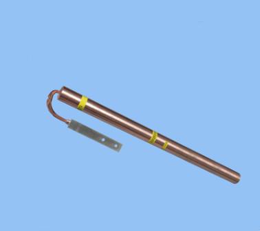
Magnesium alloy ion grounding rod
Title: Magnesium Alloy Ion Grounding Rod, Magnesium Alloy Electrolytic Ion Grounding Electrode, Corrosion-Resistant Grounding Grid
Keywords: Multi-element alloy grounding electrode, ion slow-release grounding electrode, magnesium alloy corrosion-resistant grounding electrode, single magnesium alloy ion grounding rod, combined magnesium alloy ion grounding electrode, new magnesium alloy ion grounding body, high conductivity ion grounding rod, low resistance ion grounding electrode, electrolytic ion grounding system, long-lasting ion grounding body, superconducting corrosion-resistant grounding electrode, composite nano-corrosion-resistant grounding device, lightning protection grounding system, high-quality lightning protection grounding body, latest ion grounding body, deep well ion grounding electrode, booster station lightning protection grounding body, mixing station corrosion-resistant grounding electrode, chemical plant corrosion-resistant grounding electrode, pipeline corrosion-resistant grounding electrode, light rail lightning protection grounding electrode, petrochemical lightning protection grounding, power lightning protection grounding, natural gas oilfield lightning protection grounding, oil refinery lightning protection grounding, oil tank area lightning protection grounding, etc. However, lightning protection grounding for various applications is available, including: gas pipelines, coal chemical plants, phosphorus chemical plants, State Grid, high-voltage transmission lines, substations, high-speed rail, subways, wind power generation, photovoltaic power generation, communication towers, transportation systems, computer rooms, highways, ECT (Electronic Toll Collection) systems, military bases, banks, airports, museums, schools, large stadiums, shopping malls, scenic areas, the Three Gorges Dam, Yellow River power stations, office buildings, television stations, radar stations, and dedicated ion grounding bodies for substations.
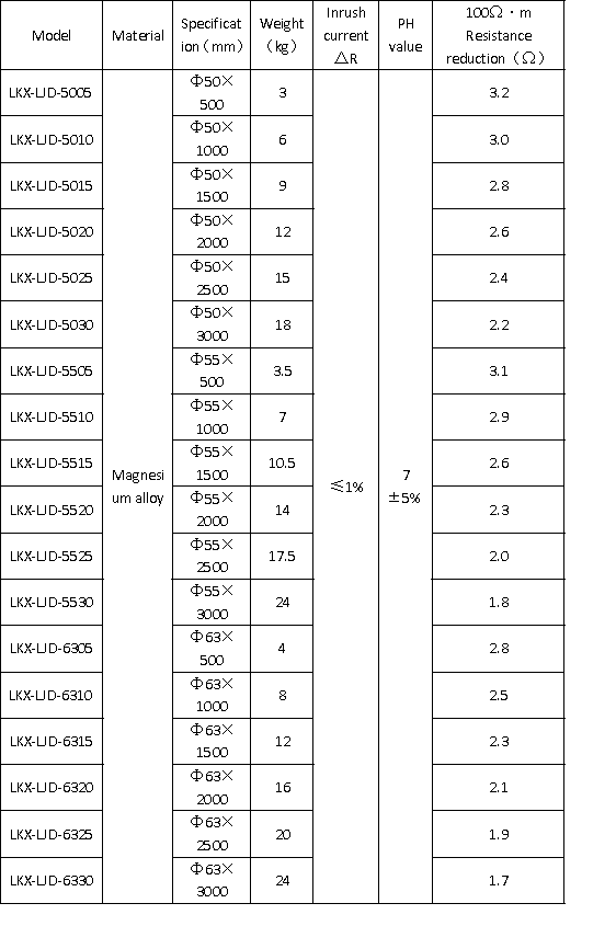
Distance: ≥5m
Temperature Range: -40℃~80℃
Product Certification: ISO9001:2000
Protection Rating: IP64
Explosion-proof Function: None
Application Scope: Lightning protection grounding
Usage Environment: Any environment
Product Introduction:
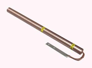
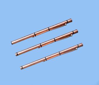
The electrolytic ion grounding electrode (magnesium alloy), with a diameter of 63mm, is a second-generation grounding resistance-reducing and corrosion-resistant ion grounding electrode.
It features a small footprint, low construction difficulty, and long-lasting and stable resistance-reducing and corrosion-resistant effects as its technological breakthroughs. Its unique
resistance-reducing technology and corrosion-resistant performance continuously improve the grounding resistance-reducing effect, making it suitable for different geological conditions.
It is especially suitable for locations with high ground resistivity, high grounding requirements, and complex grounding projects, offering excellent cost-effectiveness. This product is suitable for all lightning protection grounding projects.
Working Principle:
1. Resistance Reduction Principle
Grounding resistance is a function of earth resistivity and electrode shape and size. Therefore, reducing soil resistivity is one method to reduce grounding resistance.
The grounding resistance-reducing and corrosion-resistant ion electrode is developed using the principle of reducing the resistivity of the soil around the grounding electrode. It is made by adding corrosion-resistant properties to the original electrode and employing a new process. The electrolytic grounding electrode is composed of a Φ63mm copper tube with 4-12 ventilation holes. An environmentally friendly physical compound is filled inside the electrolytic electrode tube, allowing it to fully absorb moisture from the soil and air when buried underground. Through deliquescence, the electrolyte solution is slowly discharged from the ventilation holes, resulting in an effective and lasting reduction in the soil resistivity around the grounding electrode.
2. Corrosion Prevention Principle
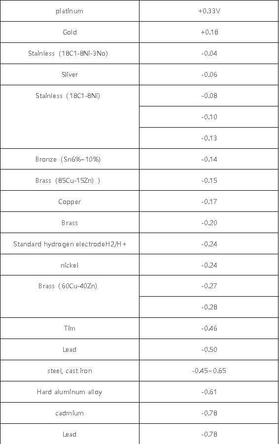
The grounding resistance-reducing and corrosion-resistant ion electrode utilizes the principle of macroscopic cell corrosion. Two metals in different locations are combined to form a cell where the base metal is the anode and the noble metal is the cathode. The anode will be corroded.
From a set of potential data for measuring metals in seawater using a saturated calomel electrode as a reference electrode (Table 1), it can be seen that using magnesium as the anode, a sacrificial anode, to protect the grounding metal is one of the most suitable methods.
Product Features:
1. Durable and won’t dissipate quickly due to rainwater or groundwater;
2. Due to the lowest magnesium potential, using magnesium alloy as the anode has minimal impact on nearby metal structures;
3. Low operating cost, achieving zero maintenance, one-time investment, long-term benefits;
4. Excellent adsorption performance, eliminating contact resistance between the grounding electrode and the soil, improving the electric field distribution in the ground;
5. Excellent permeability, penetrating deep into soil and rock crevices, forming a root-like network, increasing the drainage area in the ground;
6. The filler is a non-toxic compound, causing no environmental pollution.
Construction Guidelines:
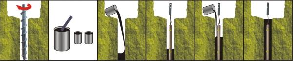
1. Drilling:
Excavate a circular pit at the selected construction site according to the product specifications, and drill holes perpendicular to the ground in the pit.
2. Preparing the Filler:
⑴. Add the appropriate amount of fresh water (well water or tap water is acceptable) to the volume, with a water-to-filler ratio of 0.4-0.6:1. (2) Add a special high-energy filler, typically a long-lasting corrosion inhibitor and resistance-reducing agent (long-lasting ionic agent: long-lasting corrosion inhibitor: active ionic agent = 25:25:1), and stir until a paste is formed.
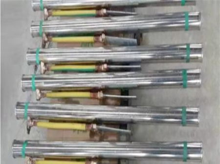
3. Remove the electrolytic ion grounding electrode from the packaging and check if the product is intact (one end of the electrolytic ion grounding electrode has a 95mm² copper wire welded to it, and a galvanized flat iron piece welded to the copper wire, with two 12mm diameter holes drilled in it, the center-to-center distance between the holes being 63mm).
4. Remove the sealing tape from both ends and the middle of the electrolytic ion grounding electrode (the sealing tape is used to seal the vent holes; the vent holes, through deliquescence, effectively release active electrolytic ions into the soil, making the grounding electrode an ion generating device, thereby improving the surrounding soil quality to meet the grounding resistance reduction requirements).
5. Fill the bottom of the hole with one-quarter of the prepared filler.
6. Insert the electrolytic ion grounding electrode into the hole, ensuring the top of the electrode is flush with the bottom of the pit.
7. Connect the lead wire: The lead wire is made of copper wire reinforced with flat iron. It can be secured with screws (after scraping off the silver paint around the hole), or the flat iron can be cut and then welded.
8. Fill the remaining filler around the grounding electrode up to 100mm from the top. Measure the grounding resistance. Once the requirement is met, cover the area around the grounding electrode with soil.
9. If one set of grounding electrodes does not meet the grounding resistance requirement, two or more sets can be used in parallel. The distance between grounding electrodes should not be less than 5m.
10. Check the installation to ensure the grounding electrode is completely buried and properly connected to the grounding grid. Measure the grounding resistance after the grounding electrode has fully absorbed moisture (24 hours).
Table 1: Sequence of spontaneous potentials of metals in seawater determined using a saturated calomel electrode as a reference electrode
Applications:
Widely used in equipment grounding, pipeline AC/DC working grounding, lightning protection grounding, and safety protection grounding in industries such as communications, power systems, building systems, military facilities, transportation systems, banking systems, computer systems, and broadcasting systems.