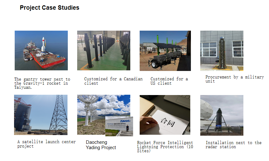
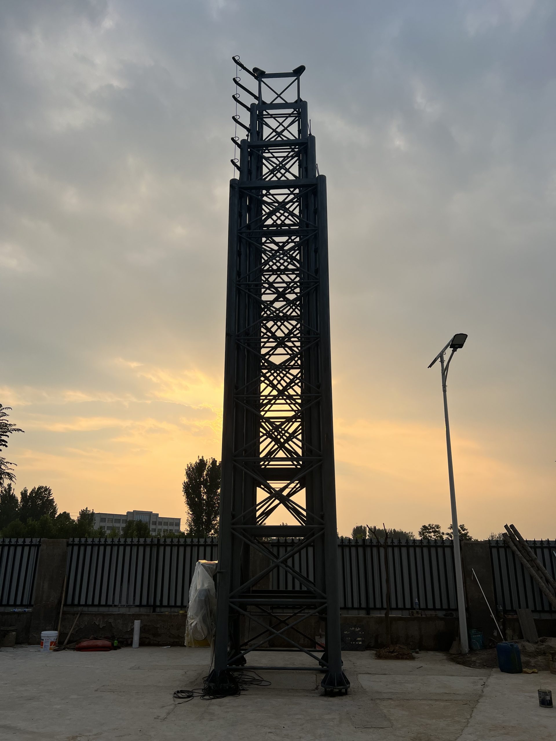
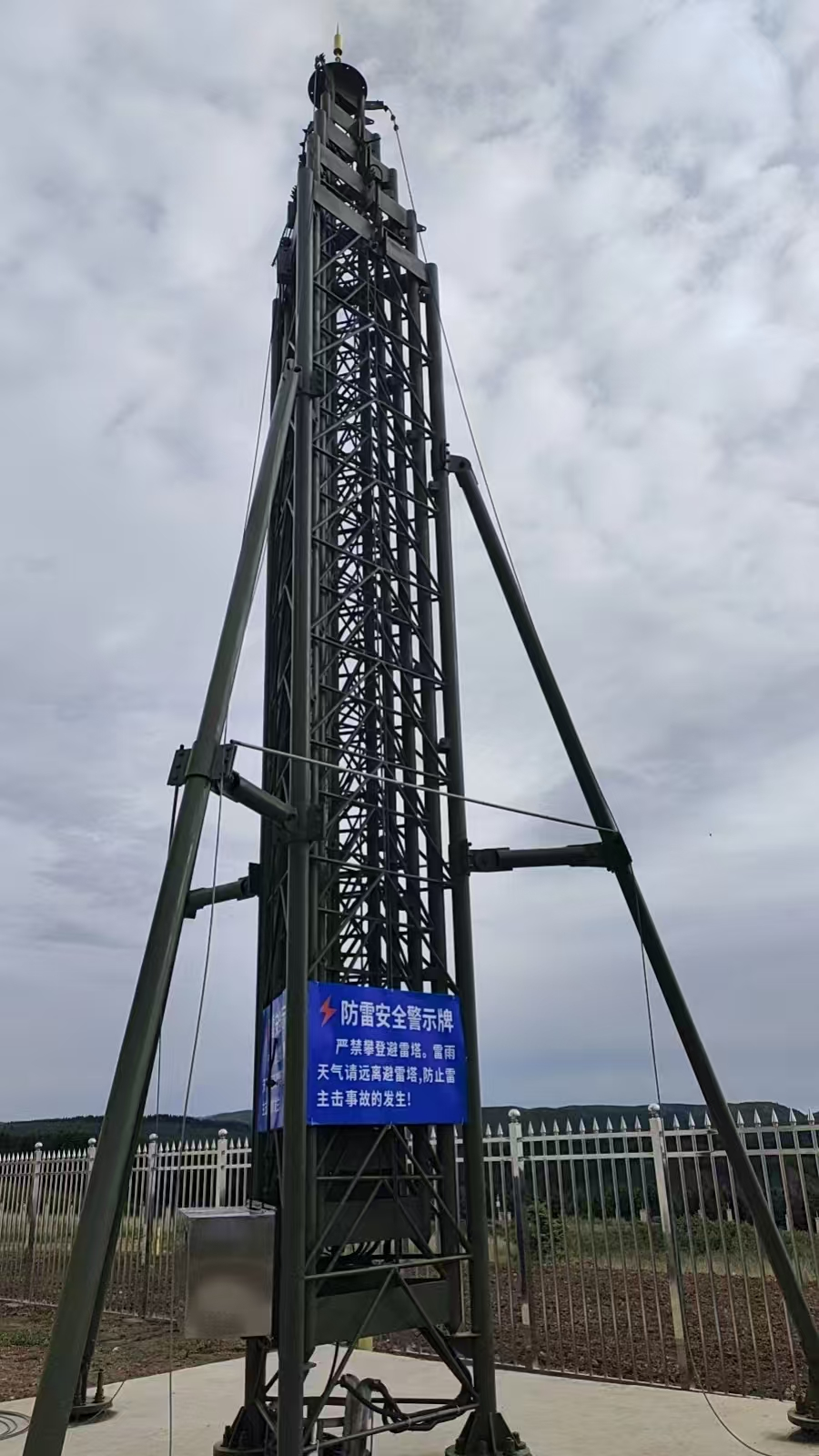
Integrated, intelligent, multi-parameter early-warning and positioning telescopic mast (trailer-mounted)
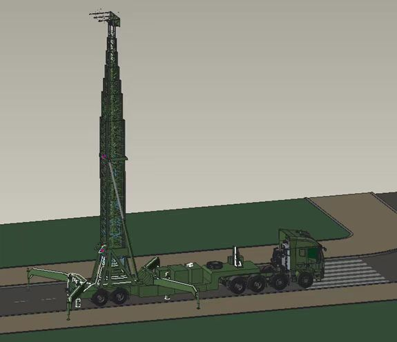
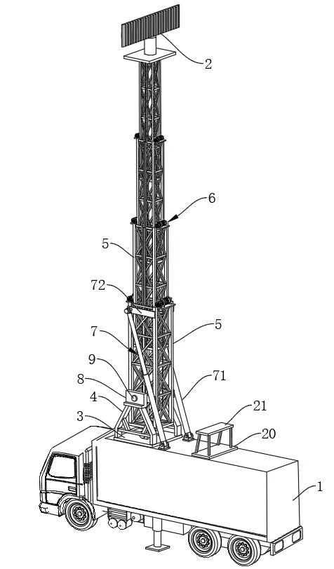
A platform—or a frangible, break-away style mount—is designed for the top of the telescopic mast. One side of this platform houses a single-station lightning locator capable of pinpointing lightning strikes with high accuracy, while the other side is equipped with multi-parameter meteorological monitoring equipment for real-time weather tracking. An alarm unit is also installed on the platform; it issues an immediate alert when the system predicts an imminent lightning strike, allowing for timely preventive measures. Additionally, an early-streamer emission (ESE) lightning rod is mounted at the top to attract lightning, thereby effectively protecting the building, equipment, and personnel.
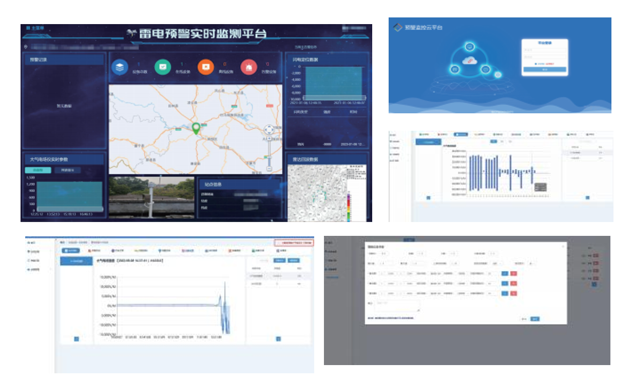
Meanwhile, the cloud platform offers comprehensive functionality, enabling the real-time display of data trends, the retrieval of alarm and historical records, and flexible alarm configuration. These features provide users with full visibility of relevant information, ensuring both safety and convenient management.
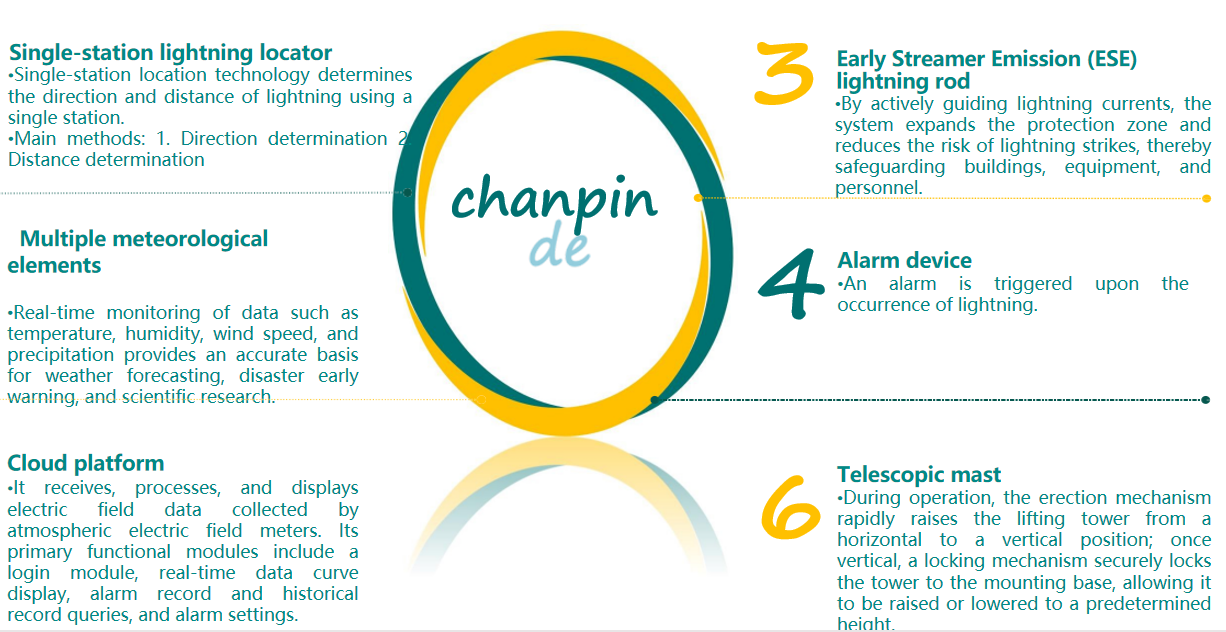
Single-station lightning locator(Determining lightning direction and distance from a single site)
Placed on the elevating top platform of the integrated, intelligent, multi-parameter early-warning and positioning telescopic mast mounted on a trailer.
1.Direction determination
Principle:
Lightning direction is generally determined using the crossed-loop cathode-ray direction-finding method.
Signals are received via two orthogonal loop antennas to determine the direction of the lightning.
2.Distance measurement
Principle: It utilizes the varying atmospheric attenuation rates of electromagnetic waves at different frequencies; by measuring the amplitudes of atmospheric electrical signals at several distinct frequencies, the distance is determined based on the ratios between them.
Multiple meteorological elements
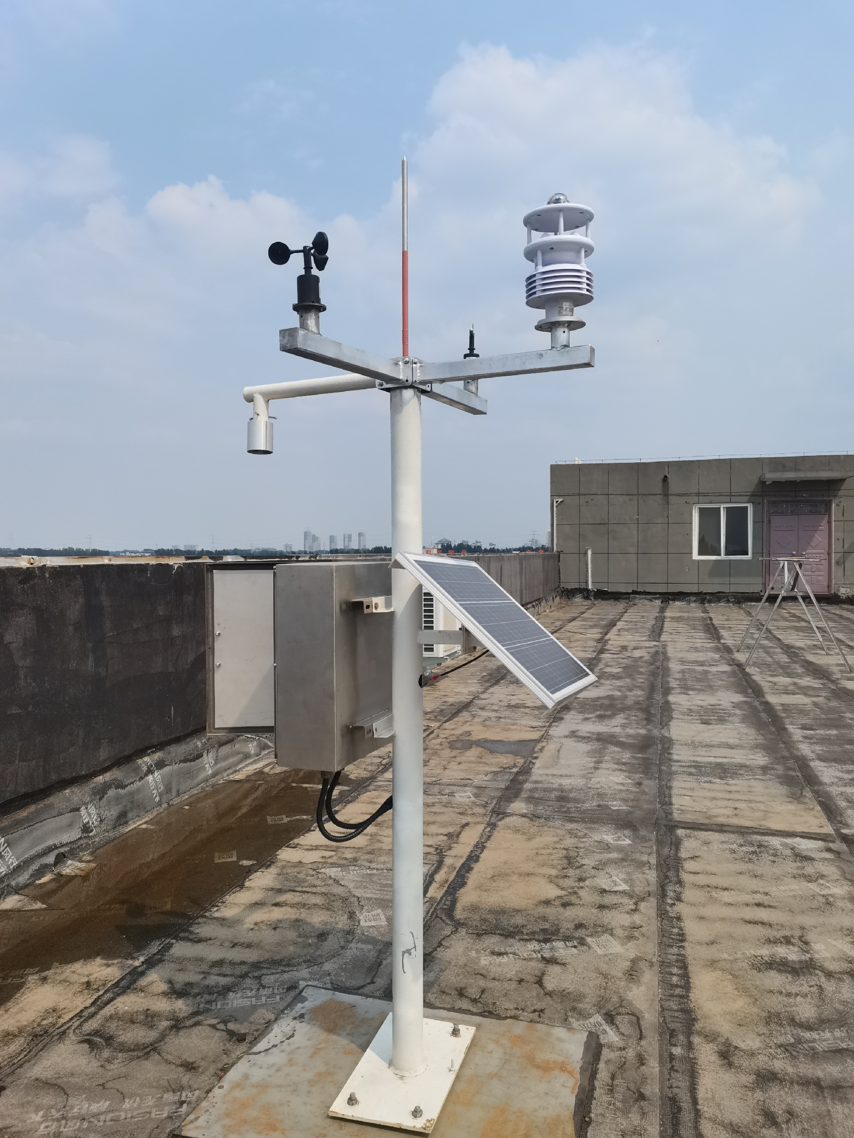
The JLT1013 is a compact weather station capable of monitoring 13 parameters: temperature, humidity, air pressure, wind speed, wind direction, PM2.5, PM10, carbon monoxide, nitrogen dioxide, sulfur dioxide, ozone, and either H2S or TVOC. Featuring a highly integrated design, it enables continuous, 24-hour online monitoring of outdoor meteorological parameters and outputs all 13 parameters to the user simultaneously via a digital communication interface.
Early Streamer Emission (ESE) lightning rod
1.Multifunctional Active Ion Lightning Protection Device
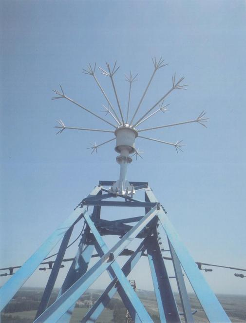
1. Active Protection: Capable of actively intervening in the formation of lightning to reduce the probability of strikes, distinguishing it from the passive lightning-attracting mechanism of traditional lightning rods.
2. Wide Coverage: Able to disperse corona ions and similar elements over a large area, providing an extensive protection radius that covers multiple objects.
3. Mitigation of Induced Lightning: Effectively reduces the hazards posed by induced lightning to electrical equipment and minimizes electromagnetic pulse interference.
2.Multiple Electric Field Compensator
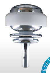
The multi-field electric field compensator is a passive sensor system designed to continuously balance and eliminate the effects of atmospheric electric fields through multiple compensation units, thereby creating a protective shield within its coverage area. It operates by compensating for and stabilizing the existing electric field in its environment; in doing so, it disrupts the formation of upward leaders, neutralizes surrounding electric charges, and safely dissipates the current into the ground at a harmless level (in the milliampere range).
Alarm device
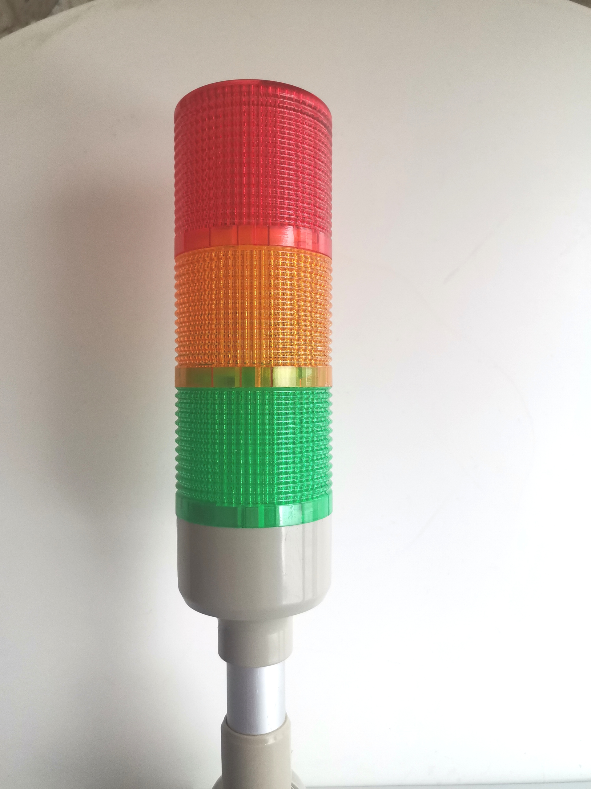
1. Query device alarm data, process the data, and update the processing status.
2. Alarms: Configure alarm parameters for devices; the platform issues an alert when a device reaches the alarm threshold.
3.Primarily displays real-time system parameters, historical records, and alarm logs.
Private platform or cloud platform
The integrated platform for meteorological monitoring, early warning, and lightning protection/disaster mitigation is a comprehensive system designed for lightning early warning and strike localization, meteorological data monitoring, intelligent power distribution management, and lightning protection equipment monitoring. Adopting a philosophy of “proactive warning, intelligent monitoring, and digital management,” the platform integrates multi-source meteorological observation data—including lightning localization systems, atmospheric electric field mills for lightning warning, automatic weather stations, and retractable lightning rod towers—with intelligent monitoring and alarm technologies. These technologies cover power supply SPD (Surge Protective Device) monitoring (including peak current, grounding resistance, soil resistivity, operating current, grid frequency, ambient temperature/humidity, backup protector status, and SPD operational status). The system supports three-level lightning warning alarms and intelligent lightning protection monitoring, as well as alerts for weather warnings and risks of flash floods and geological disasters. Key functional modules include user login, real-time data visualization (plotting), alarm record queries, historical data queries, and alarm configuration. Additionally, the platform offers cloud-based data storage and supports private deployment of the software system.
Telescopic tower mast
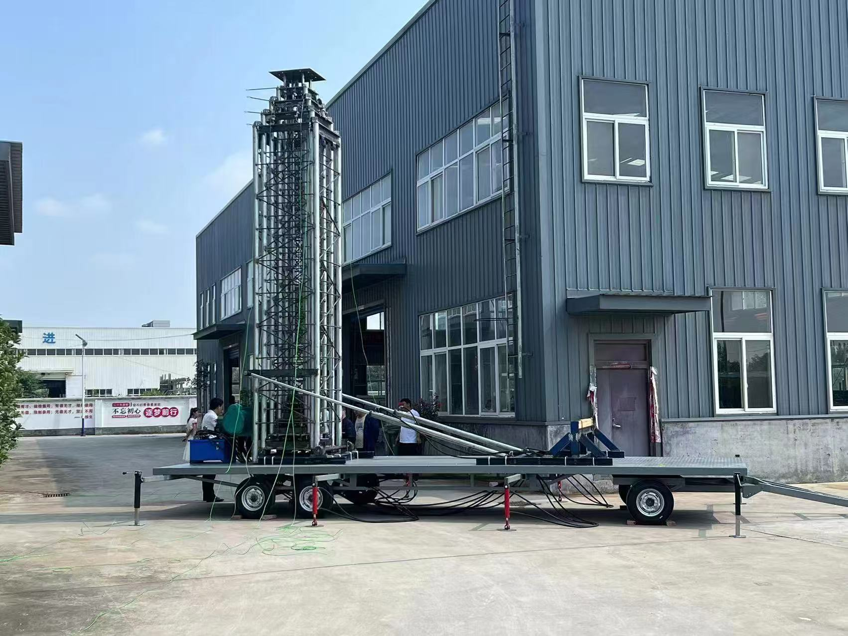
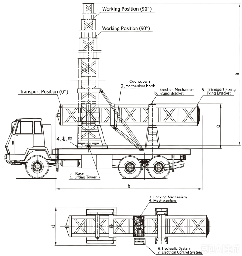
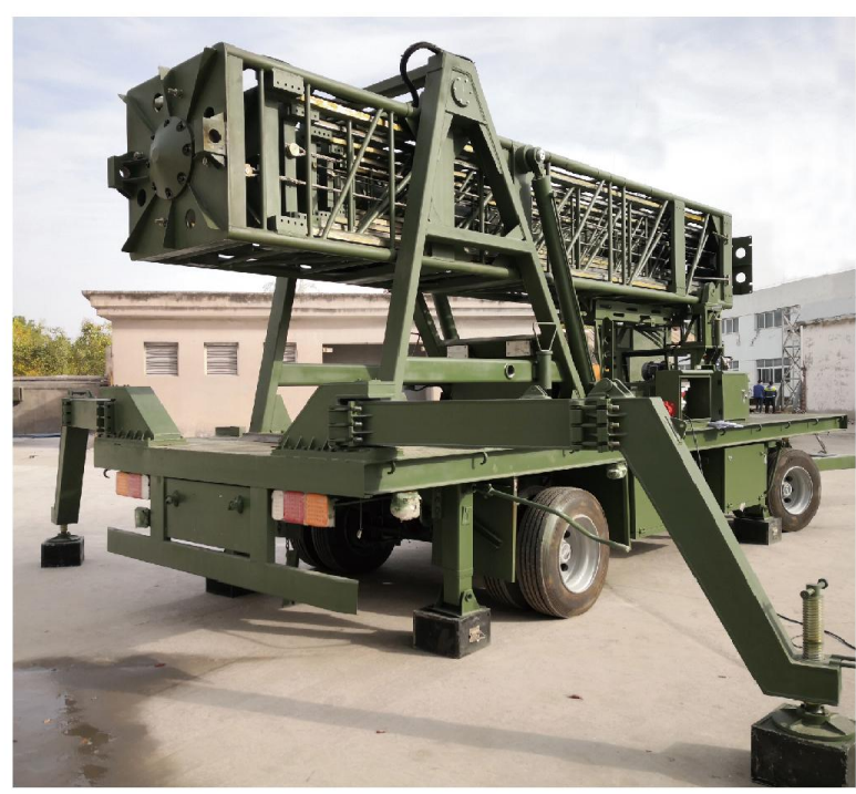
The integrated, intelligent, multi-sensor early-warning and positioning telescopic mast system—designed for trailer towing—comprises several subsystems: the telescopic tower, erection mechanism, locking mechanism, mounting base, fixed bracket, hydraulic power source, hydraulic circuitry, and electronic control system.
During operation, the erection mechanism rapidly raises the telescopic tower from a horizontal to a vertical position; once vertical, the locking mechanism securely fastens the tower to the mounting base, enabling it to be extended to the designated height.
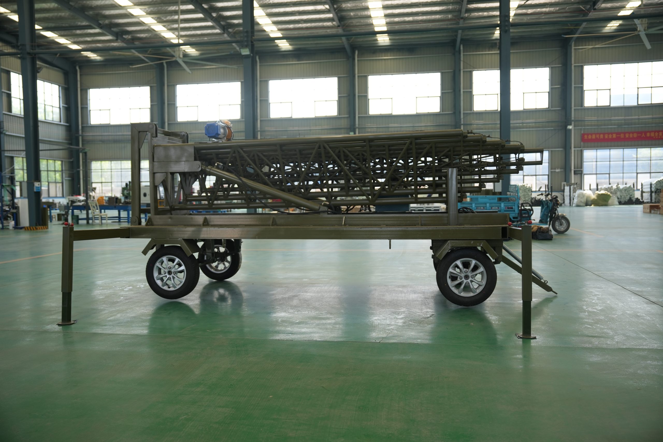
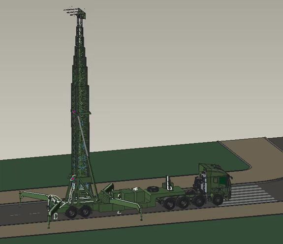
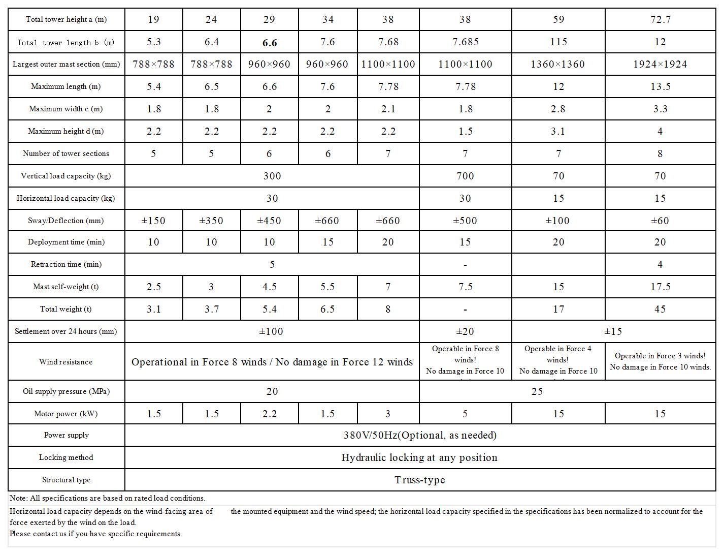
The truss-style hydraulic lifting tower system can be mounted on various vehicle platforms and is stowed horizontally during transport.
Features of the truss-style hydraulic lifting tower:
● Reduced tower weight and wind profile, resulting in enhanced stability.
● Exposed drive mechanism for easy maintenance.
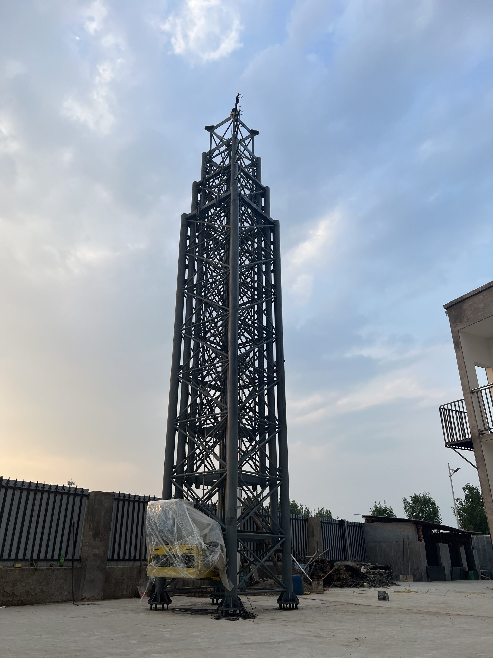
● Square cross-section design offering excellent guidance, high resistance to bending and torsion, and the capability for self-supporting operation with minimal sway and twist.
● Hydraulic locking function at the fully raised and lowered positions ensures stability without “creep” during prolonged operation. The tower top features a flange interface for equipment attachment, while the tower connects to the tilting mechanism and mounting base via a pivot shaft; in the transport position, the tower lies flat and is secured to a fixed support bracket.
The tilting mechanism, mounting base, and fixed support bracket are bolted to the vehicle platform.
Integrated, intelligent, multi-parameter trailer-mounted system featuring an extendable mast for early warning and positioning.
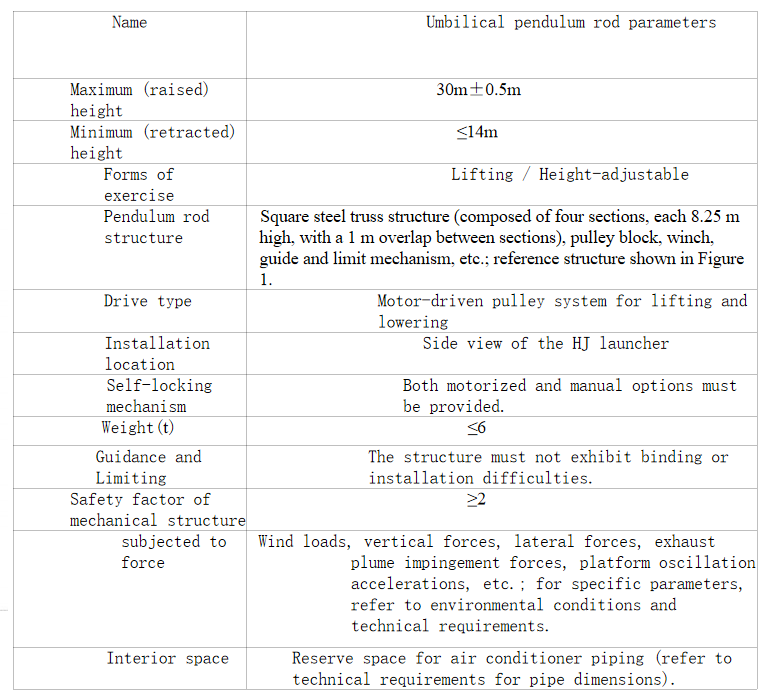
Technical specifications of the pendulum rod
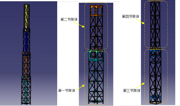
Lifting mechanism
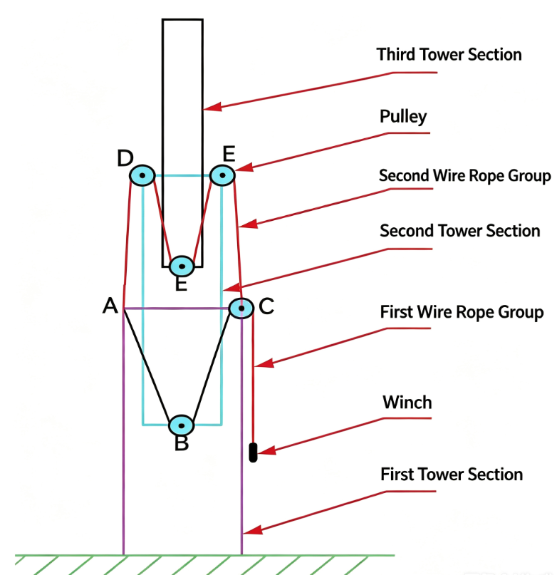
Operating Principle:
(1) The pulley at point B is a movable pulley; when the winch retracts the wire rope, point B moves upward, causing the second tower section to move upward (points D and F move upward).
(2) Since the length of the second set of wire ropes is fixed, the upward movement of points D and F necessarily lengthens the AD and FC rope segments while shortening the DE and EF segments; this results in the third tower section moving upward relative to the second tower section.
(3) Therefore, driven by the winch, the second and third tower sections can be raised or lowered simultaneously.
Functional Requirements
1. Line Protection
Prevents damage to lines caused by pulling, friction, or twisting during the lifting tower’s vertical movement.
Prevents lines from colliding with or becoming entangled in other components.
2. Accommodating Vertical Movement
Allows the umbilical swing arm to pivot flexibly with the tower’s movement during ascent or descent, ensuring lines are not excessively stretched or twisted.
3. Extending Line Service Life
Reduces bending and stretching during lifting operations, thereby minimizing fatigue damage and extending the service life of the lines.
4. Enhancing Safety
Prevents safety hazards—such as power outages, signal loss, or hydraulic system failures—caused by accidental line breakage or detachment.
5. Optimizing Equipment Operation
Ensures lines remain neatly organized during lifting, preventing interference with normal equipment operation.
Reduces equipment downtime or malfunctions caused by line-related issues.
6. Simplifying Maintenance
Facilitates routine inspection, maintenance, and replacement through centralized line management.
7. Adapting to Challenging Environments
Protects lines from environmental factors in outdoor or harsh conditions (e.g., high winds, rain, snow, or high temperatures).
Performance requirements
The key technical performance requirements are as follows:
a) Perform at least three lifting/lowering cycles per launch mission;
b) Ascent and descent times ≤ 10 min;
c) The swing arm utilizes an all-steel truss structure; to facilitate disassembly and transport, it may be designed in sections. The structure features a square cross-section, with design dimensions ≤ 1600 × 1600 mm at the base and ≤ 950 × 950 mm at the top;
d) In the operational position, the distance from the top surface of the swing arm to the top surface of the launch platform shall be 30 ± 0.5 m. The interface for the launch vehicle’s air conditioning port shall have a diameter of 300 mm, and space must be reserved within the swing arm for routing air conditioning ducts;
e) Total mass of the swing arm ≤ 6 t;
f) The swing arm must be capable of locking in place upon reaching the operational position;
g) The retraction (tilting back) motion must accommodate the pull-away force of the air conditioning connector and include a design margin for loads; the retraction process must be smooth, without shuddering or abnormal noise;
h) Swing arm retraction sequence: command issuance followed by command acknowledgment;
i) An electrical signal circuit must be provided to trigger the separation of the air conditioning connector.
Load requirements
(1) The swing arm shall ensure an adequate safety margin, with a structural safety factor of ≥2 and a deformation of ≤100 mm.
(2) It shall withstand a lateral force of 200 kg during the docking of the air conditioning interface.
(3) It shall support the load of the 200 kg air conditioning duct docking equipment mounted above the swing arm.
(4) It shall withstand an HJ exhaust plume impact force of 8 kPa.
Transportation and Installation Requirements

a) The lifting and transport of the swing arm must be supervised by designated personnel using appropriate fixtures and tooling. Precautions must be taken to prevent vibration, impact, deformation, dropping, or other forms of damage during the process;
b) The user and the designer must agree upon the arrangements for transport and lifting; the design documentation regarding transport and installation must be provided to the user for review;
c) After the launch pad has been commissioned, the swing arm is to be lifted to the hinge point on the launch pad and installed; the hydraulic and control systems must be connected, and all functional operations tested.